


How water travels up trees Teach article
Why do giant redwoods grow so tall and then stop? It all has to do with how high water can travel up their branches.

sempervirens
Photo courtesy of Allie_caulfield/
Wikimedia Commons
The redwoods of northern California, Sequoia sempervirens, are the tallest trees in the world and can grow to heights of more than 110 m. However, what finally limits their height is still debated.
The most popular theory is the ‘hydraulic limitation hypothesis’ (Ryan & Yoder, 1997), which suggests that as trees grow taller, it becomes more difficult to supply water to their leaves. This hydraulic limitation results in reduced transpiration and less photo-synthesis, causing reduced growth.
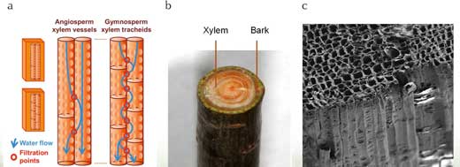
In tall trees, water supply can be limited by two factors: distance and gravity. Tall trees have a longer path- way of transport tissue – known as xylem – which increases the difficulty of water to travel, something we call hydraulic resistance. In addition, not only is the xylem pathway long, but the trees are tall and the water has to overcome gravity. Increased force is necessary to pull the water up to the highest leaves. This situation differs from a long hosepipe lying along the ground: it would have high resistance due to its length, but not the additional difficulty of being upright.
Images courtesy of Boutilier et al.
Fast-growing trees often have shorter life spans. To achieve their rapid growth, pioneer trees have wider xylem vessels, increasing their hydraulic efficiency but also increasing the risk of embolisms (air locks). Air locks in xylem vessels prevent water from being able to travel through them.
In contrast, very tall trees are often very long-lived. It is thought that this is partly because they are more likely to adopt a safe hydraulic design, with multiple narrow xylem vessels instead of a few wider ones.
This increased safety is counteracted by a decreased efficiency of water transport, which consequently limits growth rates. Tree height, therefore, may also be limited by the safety versus efficiency trade-off in xylem function (Burgess et al, 2006).
The following two activities explore the trade-off that plants make between being efficient with water transport and having a safe design. Both activities can be adapted for students aged 15–18 with a wide range of abilities, but you should assess whether the students can perform all of the experiments or whether it is safer for the teacher to do the cutting. Each activity will take about 50 minutes.
| Species | Mean xylem length/m |
|---|---|
| Acer saccharum (Sugar maple) | 0.0312 |
| Cinnamomum camphora (Camphor tree) | 0.1184 |
| Rhododendron_maximum (Great Rhododendrum) | 0.0246 |
| Vitis vinifera (Common Grape Vine) | 0.1503 |
Estimating maximum xylem vessel lengths
Comparing the lengths of the xylem vessel will allow students to predict their relative resistance to water flow.
Materials
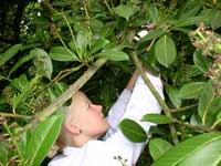
Image courtesy of Clare van
der Willigen
- Selection of recently cut branches from a tree or shrub, including any leaves or side branches, up to 2 m in initial length. If the experiment is to be performed within a few hours of harvesting, keep the plant material in a plastic bag to avoid excessive water loss.
- Rubber/silicon tubing
- Cable ties or jubilee clips
- Sharp pruning shears or scissors
- 60 cm3 syringes
- Large basin of tap water
- Hand lens
- Ruler
syringe
Image courtesy of Clare van
der Willigen
Procedure
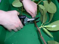
- Cut a length of branch over 1 m, making sure the cut is clean and the end of the branch is not crushed. The branch will be much longer than the xylem vessels inside.
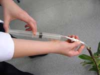
- Attach a 60 cm3 syringe, filled with air, to the proximal (wider) end of the branch using silicon tubing and cable ties as required.
- Pressurise the air in the syringe and branch by compressing the volume of air in the syringe by about half (e.g. from 60 cm3 of air to 30 cm3). This pressure must be maintained through steps 4–6.
- Hold the distal end of the branch under water.
- Use a hand lens to see if a steady stream of bubbles can be detected from the distal end of the branch.
- Progressively cut the distal end of the branch back by about 1 to 5 cm at a time, making sure each time that the end of the branch is not crushed and has a clean cut.
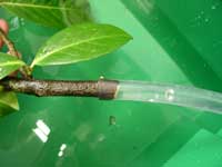
- When a stream of bubbles is observed, the length of the branch gives an approximate maximum length of the xylem vessels.
Safety Note
Students should be warned about the safety precautions necessary when using sharp objects. See also the general safety note.
Follow-up activity
Students could compare maximum xylem vessel lengths in a variety of different plants or different parts (roots, main and side branches) of the same plant. It is common for fast-growing plants to have longer xylem vessels and therefore fewer breaks between xylems. Can the students suggest why this might be?
About what happens
A branch contains several xylem vessels linked together. Between the xylem vessels are perforated wall plates. The fewer of these divisions there are, the lower the resistance and the faster water can travel.
A detailed study of vessel length in Chrysanthemum stems (Nijsse et al, 2001) and in a wide range of shrubs and trees (Jacobsen et al, 2012) can be used for cross-reference.
Measuring xylem hydraulic conductivity
Measurements of xylem hydraulic properties show how well plants can supply water to their leaves. It is possible to measure the hydraulic conductance of stems, branches and roots in the classroom with some simple, inexpensive equipment. To measure hydraulic conductivity, the branch length should be longer than the mean length of the xylem vessels (see previous activity).
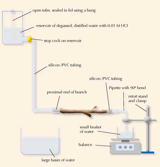
Image courtesy of Nicola Graf
Materials
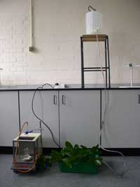
Image courtesy of Clare van
der Willigen
- Selection of recently cut branches from a tree or shrub investigated in the previous experiment. Ensure that the pieces are longer than the longest xylem vessels measured. If the experiment is to be performed within a few hours of harvesting, keep the plant material in a plastic bag to avoid excessive water loss.
- Rubber/silicon tubing
- Cable ties or jubilee clips
- Sharp secateurs, scissors or a large scalpel
- Chopping board
- Large basin of water
- Metre rule
- Reservoir of degassed, distilled water in a container with a tap at the bottom. Degas the water by boiling it or using a vacuum pump for approximately 1h until all the gas has been expelled from the water. Air bubbles in water that is not degassed may block the xylem vessels.
- Hydrochloric acid
- 1 cm3 pipette (a pipette with a 90o bend is most effective. A standard glass pipette can be bent in a very hot flame)
- 50 cm3 plastic beaker
- Retort stand and clamp
- Balance (precision of at least 0.01 g)
- Stop watch or stop clock
water
Image courtesy of Clare van
der Willigen
Procedure
1. Set up the apparatus as illustrated in the diagram above:
a Add hydrochloric acid to the degassed, distilled water to give a final concentration of 0.01 M. For example, add 0.5 cm3 of 0.1 M HCl to 5 dm3 degassed, distilled water. Hydrochloric acid prevents the long-term decline in conductance by reducing microbial growth in the xylem.
Safety tip
Remember to always add acid to water, not water to acid.
b Fill the reservoir with the acidified water. Insert a piece of tubing, sealed at one end with a bung, into the top of the reservoir. The open tubing ensures a constant pressure head because even if the water level drops, the effective height of the reservoir will remain the same.
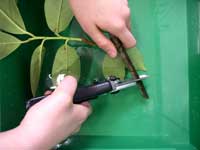
Image courtesy of Clare van
der Willigen
c To the tap of the reservoir, add some tubing, fill with water from the reservoir, seal the open end and place into the large basin of water.
d Close the tap.
e Submerge the proximal end of the branch in the large basin of water. This is the end of the branch that was nearest to the main stem of the plant.
f Cut approximately 3 cm off the proximal end of the branch under water to ensure that no air pockets remain in the xylem. Shave off the end of the cut using a sharp blade.
g Connect the newly cut end of the branch to the water-filled tubing attached to the reservoir under water. If the bark is very rough, it can be stripped back prior to connection. A water-tight seal should be achieved using cable ties or jubilee clips if necessary, however do not over-tighten and compress the xylem vessels.
water
Image courtesy of Clare van
der Willigen
h Submerge the other end of the branch in the tub of water.
i Cut approximately 3 cm off the end of the branch under water to ensure that no air pockets remain in the xylem. Shave off the end of the cut using a sharp blade.
j Measure and record the length of the branch. Ensure it is longer than the maximum xylem vessel length (see previous experience).
k Connect the bent pipette to more rubber tubing and sub- merge into the basin of water.
l Connect the newly cut end of the branch to the water-filled tubing attached to the pipette as above.
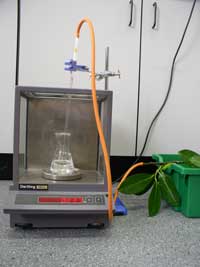
m Fill the 50 cm3 beaker with water and place on the pan balance.
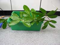
Image courtesy of Clare van
der Willigen
n Take the branch end and pipette out of the basin of water with the end of the pipette sealed.
o Place the end of the pipette in the 50 cm3 beaker on the balance.
p Use the retort stand and clamp to hold the pipette in place. The tip of the pipette should not lean on the bottom of the beaker, but should be below the water level. This ensures that as the water drips through the branch, there is a smooth increase in the mass of water in the beaker.
2. Open the tap from the reservoir.
3. Measure the mass of water every 30s for 3 min.
4. Measure the effective height of the reservoir using the metre rule. This is the height from the bottom of the open tubing in the reservoir to the proximal end of the branch.
Safety Note
Students should be warned about the safety precautions necessary when using sharp objects and acids. See also the general safety note.
balance
Image courtesy of Clare van der
Willigen
Analysis
Hydraulic conductivity is measured as the mass of water flowing through the system per unit time per unit pressure gradient (Tyree & Ewers, 1991). The hydraulic conductivity of the branch, kh, is calculated using the following formula:
kh = (flow rate x branch length)/hydrostatic pressure head
where the flow rate is measured in kilograms per second (kg/s); branch length in metres (m); and the pressure head in megaPascals (MPa). To calculate the flow rate, plot the mass of water (in kg) measured in step 3 against time (in s). The flow rate will be the gradient of the line of best fit (in kg/s). See table 2 and figure 1 for a worked example.
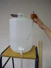
Image courtesy of Clare van der
Willigen
The hydrostatic pressure head is found by multiplying the effective height of the reservoir, measured in step 4, with the density of liquid and the acceleration due to gravity. The density of the acidified water can be assumed to be 1000 kg/m3 (at room temperature) and a value of 9.81 m/s2 can be used for acceleration due to gravity. Thus, with an effective height of the reservoir of 1m, the hydrostatic pressure head would be 1000 x 9.81 x 1 = 9810 Pa or 0.00981 MPa.
Remember, maximum hydraulic conductivity is only achieved if none of the xylem vessels are embolised (filled with air). To try to prevent this, branches can be flushed with water at a pressure of approximately 200 kPa for 20 min before measuring conductivity. Alternatively, ensure that branches are selected from well-watered trees and that the leaves are covered in a large plastic bag prior to measurement.
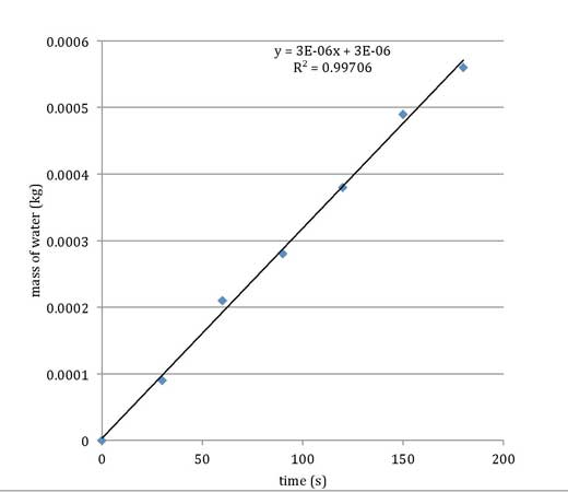
plot to calculate flow rate.
Data from table 2.
Remember, maximum hydraulic conductivity is only achieved if none of the xylem vessels are embolised (filled with air). To try to prevent this, branches can be flushed with water at a pressure of approximately 200 kPa for 20 min before measuring conductivity. Alternatively, ensure that branches are selected from well-watered trees and that the leaves are covered in a large plastic bag prior to measurement.
| Flow rate (kg/s)- see figure 1 | Branch length (m) | Hydrostatic pressure head (MPa) | Hydraulic conductivity kh (kg m/MPa s) |
|---|---|---|---|
| 3 x 10⁻⁶ | 0.32 | 0.0147 | 6.53 x 10⁻⁵ |
Follow-up experiments
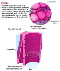
Image courtesy of Kelvinsong/Wikimediacommons
Investigations on different levels of water stress on the same, or similar, branches would give an indication of plants that are more vulnerable to cavitation, or air bubbles. Hydraulic conductivity can change de- pending on environmental conditions, and the same species of plant that have adapted to different environments could be tested in the laboratory or in the field. Compare branch cross-sections of different diameter or those supporting different leaf areas.
Students could observe the effect on hydraulic conductivity of changing the branch length and relate this to the height of the plant. They could also investigate the effect on the flow rate of changing the height of the reservoir. The reservoir height (pushing force) could be considered as equal, but opposite, to the pulling force created by the low water potential in xylem vessels.
Did you know?
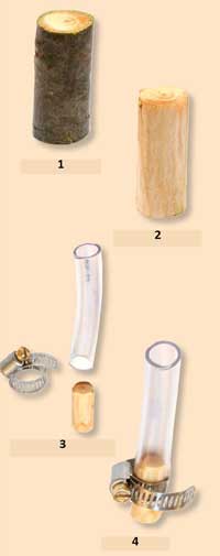
2- Peel off bark
3- Fasten into tube
4- Xylem filter
Image courtesy of Boutilier et al.
Xylems are essentially porous filters, and scientists think that they could be used to filter water and make it safe to drink. Earlier this year, a group at the Massachusetts Institute of Technology in the USA showed that a 3cm3 piece of pine branch could act as a filter and remove 99.9 % of bacteria from water, at a rate of several litres a day. The technique isn’t perfect yet: viruses and chemical contamination can’t be stopped by twigs, but the work by Boutilier et al. (2014) suggests a cheap way to purify water in developing countries.
References
- Boutilier M.S.H., Lee J., Chambers V., Venkatesh V., Karnik R. (2014) Water Filtration Using Plant Xylem. PLoS ONE 9(2): e89934
- Burgess S.S., Pittermann J., Dawson T.E. (2006) Hydraulic efficiency and safety of branch xylem increases with height in Sequoia sempervirens (D. Don) crowns. Plant, Cell and Environment 29(2): 229-239. doi: 10.1111/j.1365-3040.2005.01415.x
- Jacobsen A.L., Pratt R.B., Tobin M.F., Hacke U.G., Ewers F.W. (2012) A global analysis of xylem vessel lengths in woody plants. American Journal of Botany 99: 1583-1591 doi: 10.3732/ajb.1200140
- Nijsse J., van der Heijden G.W.A.M., van Leperen W., Keijzer C.J., van Meeteren U. (2001) Xylem hydraulic conductivity to conduit dimensions along chrysanthemum stems. Journal of Experimental Botany 52: 319-327 doi: 10.1093/jexbot/52.355.319
- Ryan M.G., and Yoder B.J. (1997) Hydraulic limits to tree height and tree growth. BioScience 47(4): 235-242 doi: 10.2307/1313077
- Tyree M.T., Ewers F.W. (1991) The hydraulic architecture of trees and other woody plants. New Phytologist 19: 345-360
Resources
- For a scientific analysis of maximum possible tree heights, see:
- Koch G.W., Sillett S.C., Jennings G.M., Davis S.D. (2004) The limits to tree height. Nature 428: 851–854. doi: 10.1038/nature02417; freely available
Review
The article describes two experiments that can easily be conducted in science classrooms or laboratories to study water movement in plants.
Although the procedures are easy to carry out, the concepts and knowledge that are explored aren’t so simple, but are appropriate for upper secondary-school students (aged 15-18). In my experience, there are not very many procedures that consider water movement for this age group, so many science teachers will welcome this article.
There are also relevant opportunities for interdisciplinary teaching involving mathematics in particular. It would be quite interesting to use this experiment as a starting point to introduce students to the development of a database and subsequent statistical analysis (not too complex). For example, students could estimate maximum xylem vessel lengths and measure xylem hydraulic conductivity of different plants and at different times (e.g. winter vs. summer). This database could be extended from year to year with other students. Such a strategy could help students to understand science as a collaborative activity – not only between different disciplines but also between different ‘generations’ of scientists.
Betina Lopes, Portugal