


Simulating the effect of the solar wind Teach article
The smooth operation of communications satellites can be influenced by solar weather. Mimic this effect on a smaller scale in the classroom with a simple demonstration.

Brohi/Wikimedia Commons
It’s the final of the 2014 football World Cup, the score is tied and there is no time left on the clock. Fans all over the world hold their breath, but suddenly all the TV sets in Europe go black! What can cause this to happen?
Keeping connected
Let’s start from the beginning. How is it possible to watch, almost in real time, an event taking place thousands of kilometres away? The answer orbits above our heads: satellites.
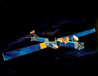
Image courtesy of US Air Force/
Wikimedia Commons
Since the launch of Telstarw1 in 1962, satellite communication has continued to grow. Today, even when news or sport events are taking place just a few kilometres from a TV studio, the camera signals are probably being transmitted using a satellite in geostationary orbitw2 (this means that the satellite orbits Earth at the same speed as Earth rotates, so it stays above the same position on Earth). For you to watch the final of the World Cup in Rio de Janeiro while sitting at home in Europe, a number of satellites have to work together. However, the environment far above Earth’s surface is harsh: there is no atmosphere, lots of cosmic radiation, and extreme temperature variations between sunlight and shadow. Telecommunication satellites contain state-of-the-art technology to cope with these extreme conditions, but a sneaky enemy can still threaten the operation of a satellite: the solar wind.
Solar wind and satellites
The solar wind is a stream of charged particles, mainly electrons and protons, that are released from the very hot corona, the upper atmosphere of the Sun. The particles escape the Sun’s gravity because of their high kinetic energyw3. This stream of particles reaching Earth varies in density, temperature and speed, depending on time and longitude.
When these particles approach Earth, they can have various effects: from spectacular aurorae to great geomagnetic storms. As geostationary satellites are near the edge of Earth’s protective magnetism, they can be exposed to these storms.
In the classroom
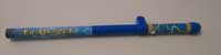
Image courtesy of Thedoros
Pierratos
The effect of the solar wind on telecommunications is a modern issue that can trigger students’ interest in space technology and space weather. But how can we mimic it in the classroom? How can we simulate the solar wind?
The Fun Fly Stick toy (figure 1) is a portable wand-like version of the Van de Graaff generator. When switched on, a belt moves inside the Fun Fly Stick and a static charge builds on the wand. Instead of the metal dome of the Van de Graaff generator, the charge accumulates on a cardboard tube. Cardboard has a high electrical resistivity but becomes a conductor when subjected to high-voltage electricity. Furthermore, it discharges more slowly than metal, so the shocking discharge sensation is eliminated.
axel on the Fun Fly Stick
Image courtesy of Thedoros
Pierratos
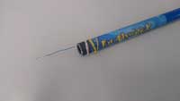
We can safely use this toy to simulate solar wind by placing a large needle or thin metal axle on the end of the control tube (figure 2). Positive electrostatic charges formed on the cardboard tube are concentrated at the tip of the needle and so ionise the air nearby. Negative ions in the air will rush towards the needle tip and positive ions will move away due to electrostatic repulsion. The movement of these ions creates a form of an ‘electric wind’ or, for the purpose of our simulation, a ‘solar wind’.
effect of the solar wind on
an electrical circuit
Image courtesy of Thedoros
Pierratos
To demonstrate the effect of the laboratory-made solar wind, we can just use a test screwdriver. Ask your students to imagine that the simple electrical circuit built into this screwdriver (usually including a battery supply and a red LED) is part of the electronic equipment of an orbiting satellite transmitting their favourite TV show. What will happen if we turn on the generator and come close (about 1 metre or less) to the test screwdriver? The red LED starts glowing (figure 3), and as the stick approaches the screwdriver it glows more and more brightlyw4! The electric circuit starts to overload. What could be the effects of a solar storm on the electronic circuits of a satellite?
Carrying light on a sound beam
light beam
Image courtesy of Thedoros
Pierratos
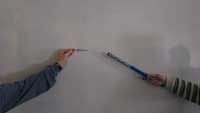
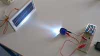
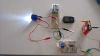
As well as overloading and possibly damaging the electronic circuits in a satellite, the solar wind could disrupt the live streaming of the World Cup final. To show this experimentally, we first have to observe that electromagnetic waves can carry usable information. To do this, we propose a modified version of the experiment described by Bernardelli, 2010 (figure 4).
Instead of using a laser pointer and a photo-diode, we use a LED flashlight (torch) and a small solar panelw5. In this way, we reduce the distance that the sound is transmitted but make a stronger impression on the students: most of them consider a laser beam to be something special, but by using a normal flashlight, we can focus on the science behind the phenomenon.
Carrying light on a sound beam
flashlight
Image courtesy of Thedoros
Pierratos
Materials
Transmitter
- LED flashlight (torch)
- 2 alligator clips
- 3.5 mm stereo plug
- Breadboard
- 100 Ω resistor
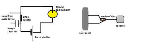
Fig 6. A diagram of the
‘carrying sound’ circuit
Image courtesy of Thedoros
Pierratos
- 100 μF capacitor
- Mp3 player with a 3.5 mm jack output
- Battery holder
- 3 1.5 V batteries (depending on the flashlight you use)
- Soldering iron
- Solder
circuit
Image courtesy of Thedoros
Pierratos
Receiver
- Solar panel
- Amplifying speakers with external power supply
- 2 alligator clips
Procedure
Transmitter
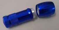
- Unscrew the head of the flashlight (figure 5).
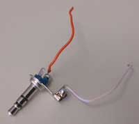
Image courtesy of Thedoros
Pierratos
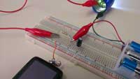
- Use the breadboard to construct the circuit shown in figure 6. Your circuit should look like the one in figure 4 (instead of using a breadboard, you can construct the circuit using alligator clips to make the proper connections). Be careful to connect the head of the flashlight and the battery holder exactly as it looks in figure 7. The negative pole of the battery holder (black wire) must be connected with the side body of the flashlight’s head while the positive pole (red wire) must be connected with the spring-like metal in the centre of the head. Otherwise, the flashlight will not turn on.

solar panel (above) to the
3.5mm speaker plug (below)
Image courtesy of Thedoros
Pierratos
- To connect the stereo plug to the breadboard, solder the two pieces of wire to the stereo plug. Solder one wire (red) to both the first and second segments of the plug (or in just one of them) while the other wire (white) goes to the third segment (figure 8).
Receiver
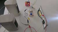
- Connect the two wires from the solar panel’s output to the 3.5 mm stereo plug or socket of the speakers using two alligator clips (figure 9a,b). Your circuit should look like the one in figure 10.
How it works
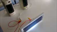
Image courtesy of Thedoros
Pierratos
The flashlight batteries provide a strong but constant direct current (DC) to the LEDs. As a result, the LEDs glow with a fixed brightness. When the mp3 player is turned on, it adds a weak but fluctuating electrical signal to the constant current from the battery. The LEDs flicker in sync with the output from the player. The stronger battery current of the flashlight is added to the weaker signal from the player (the capacitor protects the player from being overheated by the input DC). These fluctuations are picked up by the solar panel and are converted into electrical pulses that are turned back into sound by the speaker. This whole process is amplitude modulation (AM). It is the same principle used for transmitting AM radio signals.
With the screwdriver demonstration above, we showed that the solar wind could overload and probably damage a subtle electronic circuit on board a telecommunications satellite. To repeat our classroom simulation without ruining equipment, we designed and built a simple electronic circuit (box 2).
A switch activated by the solar wind
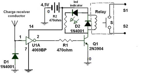
Fig 11. The diagram of a
switch that is triggered by
electric charges
Image courtesy of Thedoros
Pierratos
Materials
- 470 Ω resistor
- 2 1N4001 diodes
- 1 2N3904 transistor
- 1 CD4069 cmos inverter gate chip containing a U1A gate
- 4.5 V battery or 3–12 V DC power supply unit
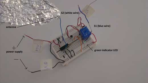
Fig 12. The switch circuit
that is activated by the
solar wind
Image courtesy of Thedoros
Pierratos
- 1 relay coil (3–12 V depending on power supply) with one NC contact
- 1 green LED (as an indicator)
- 2 alligator clips
- One small breadboard
Procedure
- Construct the circuit in figure 11; the result will look something like figure 12. In this circuit, an optional small piece of aluminium foil has been attached to the wire. This piece of foil plays the role of an antenna (the charge receiver conductor) to increase the sensitivity of the switch.
is connected to the
transmitter
Image courtesy of Thedoros
Pierratos
- Use two alligator clips to connect the 4.5 V battery (or the power supply) to the corresponding red and black wires (figure 12). The green indicator LED turns on.
- Interconnect this circuit to the ‘sound carrying’ circuit from box 1. This can be done in one of two ways:
a. In series with the transmitter circuitw6 (to show the effect of the solar wind on the circuit in a satellite that is responsible for transmitting the signal);
b. In series with the receiver circuitw7(to reflect the effect of the solar wind on the circuit in a satellite that is responsible for receiving the signal from another satellite or from the ground station).
To do so, insert the switch circuit (using the wires S1 and S2 shown in figure 12) to the transmitter or receiver as in figures 13 and 14.
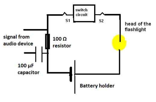
Fig 13b. The diagram of
the circuit presented in 13a
Image courtesy of Thedoros
Pierratos
- Turn the circuit on and move the charged stick towards and away from the circuit and note what happens.
About what happens
The circuit is in fact a switch triggered by the charges on the cardboard tube of the Fun Fly Stick. When the stick approaches the circuit, the induced electric charge turns on the relay and interrupts transmissionw6: according to our scenario, the solar wind has just hit a satellite and the transmission of the World Cup final has stopped. As soon as you turn off the charge, the relay turns off too, and the transmission resumes: the damage experienced by the satellite is negligible and reversible.
connected to the reciever
Image courtesy of Thedoros
Pierratos
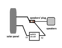
Fig 14b. The diagram of the
circuit presented in figure
14a
Image courtesy of Thedoros
Pierratos
The concepts of space weather and satellite technology are not part of the curriculum, at least not in Greece. However, space-related topics can increase students’ interest in science (Spencer & Hulbert, 2006). An obvious problem for teachers is how to demonstrate effects of this scale and intensity in a classroom. In this article, we hope to convince you that all it takes is a toy and some basic skills in constructing a simple electronic circuit.
References
- Bernardelli A. (2010) Stage lights: physics and drama Science in School 17: 41–45.
- Spencer P., Hulbert G. (2006) The Education and Skills Case for Space. Swindon, UK: Particle Physics and Astronomy Research Council.
Web References
- w1 – Learn more about the Telstar communication satellites.
- w2 – Read more about the orbits used for situating telecommunication satellites.
- w3 – Read more about solar wind.
- w4 – Watch a brief video of the effect of the Fun Fly Stick on a test screwdriver.
- w5 – Watch a video showing the transmission of sound using this experimental set-up.
- w6 – Watch a descriptive video of the disruption of the transmitter circuit.
- w7 – Watch a descriptive video of the disruption of the receiver circuit.
- w8 – Read more about ESA.
Resources
- To find out more about how the sun produces solar wind, you might like to read:
- Green L. (2008) Research into the Sun’s atmosphere Science in School 8: 52-55.
- To model a more attractive result of the solar wind – the aurorae (northern and southern lights) – read:
- Jeanjacquot P., Jean Lilensten J. (2013) Casting light on solar wind: simulating aurorae at school. Science in School 26: 32-37.
- The simulation described above is part of an integrated educational scenario entitled ‘Sherlock Holmes on board the ISS’, which was presented at the European Space Agency (ESA)w8 summer workshop held in ESTEC, Noordwjik, The Netherlands, on 21 to 25 August 2013.
- Stay informed about the sensitivity of future European space missions to the space environment.
- Keep up-to-date with the current space weather.
Review
Modern communications make much use of geostationary satellites, but these are always at risk from severe storms in the solar wind (a stream of high-energy charged particles from the Sun’s outer atmosphere). This article describes pleasant, straightforward experiments to model the effect of solar wind on data communication by light beams. The activities are well worth using with science or physics groups of students about 14 years and older in their spare time (e.g. science club, holiday activities / summer school, or lessons after exam time).
Eric Deeson UK