


Build your own radio telescope Teach article
Astronomers use giant radio telescopes to observe black holes and distant galaxies. Why not build your own small-scale radio telescope and observe objects closer to home?
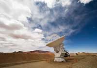
one of the giant antennas of
ALMA, the largest ground-
based astronomy project in
existence
Image courtesy of Iztok
Bončina / ALMA (ESO / NAOJ
/ NRAO)
When astronomers study the sky, they don’t just look at starlight. Stars, planets and nebulae shine across the whole electromagnetic spectrum, and the light that human eyes can see is only a narrow part of it.
Radio telescopes observe the sky for radiation at wavelengths that are thousands to millions of times longer than visible light. The huge antennas that scientists have built to observe these wavelengths have become icons of modern technology. Arecibo Observatory, so big it was built into a bowl-shaped valley in Puerto Rico, is instantly recognisable from the James Bond movie GoldenEye, while Jodrell Bank has dominated the skyline of Manchester, UK, for half a century.
The resolution of a telescope’s images depends both on the wavelength at which it operates and on the diameter of its dish. The longer the wavelength, the worse the resolution; and the larger the diameter, the better the resolution. Radio waves have a much longer wavelength than visible light, which is one reason why professional radio telescopes are enormous. Their huge size also helps them to capture the faint radiation from dim and distant objects. Nonetheless, the basic technology behind radio telescopes is quite simple and with some cheap equipment and simple tools, it’s quite easy to build a simple but functional one of your own.
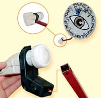
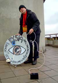
I called my radio telescope design RYSIA (a girl’s name), or RadiowyY Śliczny Instrument Astronomiczny – Polish for ‘beautiful radio astronomy device’. With RYSIA, you can carry out simple observations of objects that radiate brightly in the radio spectrum. This includes the Sun, our own planet, and man-made communications satellites such as Hot Bird, Astra and Sirius.
Materials
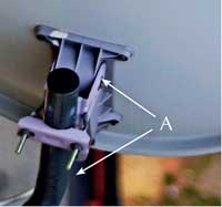
(A) at the back of the
satellite dish
Image courtesy of Boguslaw
Malański
Local scrapyards, shops selling second-hand TV equipment and online auction sites such as eBay are good places to buy the parts you need.
- A satellite receiver dish When you watch TV, the satellite dish focuses the transmissions from the satellite onto the receiver. In your radio telescope, the dish will serve a similar purpose: it will reflect the relatively faint radio waves onto the receiver. I recommend one with a diameter of at least 1 m. The dish can be of offset or parabolic type. A new dish costs approximately 100 zł (€24). A used dish should cost no more than 12-20 zł (€3-5). You can also search at scrap metal yards – this is where I found mine.If the satellite dish has a mount, remove it (figure 1), as it just adds weight and makes it harder to move. The employee at the shop or scrap yard will probably be happy to remove it for you. Leave the arm attached, though.
- A low noise block downconverter, or LNB LNBs are an essential part of satellite TV receivers, and sit at the point where the dish focuses incoming rays. When we watch TV, the LNB receives and amplifies the signal, strips out unwanted frequencies and then converts the signal to a lower frequency. In your radio telescope, the LNB will be the receiver that detects the radio waves reflected by the dish. Any brand or model will work fine, even the cheapest. The price of a new downconverter is approximately 40 zł (€10), but they can be bought second-hand for a fraction of the price.
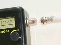
- Satellite signal meter (figure 2)
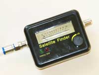
Figure 2: A satellite signal
meter
Image courtesy of Szymon
MalańskiThis tells us whether the LNB is receiving a signal, and if so, how strong it is. Be sure to get one that emits a sound when the antenna receives a strong signal; this makes it easier to demonstrate the device to large groups of students since everyone will be able to hear the signal. Additionally, the meter needs to be equipped with a dial or display that will allow you to measure the strength of the signal, so that you can make more precise measurements and compare different observations. Apart from these considerations, get the simplest and cheapest one you can find – the cost of this part is approximately 20 zł (€5).
- 3 m of coaxial cable – 5-10 zł (€1-2)
- 3 BNC (Bayonet Neill-Concelman) connectors for the coaxial cable – 60-120 gr (15-30 ¢) each. If possible, choose ‘twist-off’ connectors, as they do not need soldering.
- A power source that provides 12 V to 18 V DC
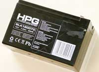
Figure 3: A power source for
your radio telescope
Image courtesy of Szymon
MalańskiI used a 12V lead-acid car battery (figure 3). You can also use standard AA batteries connected in series
Building your radio telescope
Once you have your materials, it is mostly a matter of fitting or plugging them together.
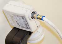
- Mount the low noise block downconverter on the arm of the antenna, using the attachments provided (figure 4).
- Cut the coaxial cable in half. Attach a BNC connector to each end of one piece of cable, and to one end of the other (figure 5).
- Take the coaxial cable that has two connectors and plug one end into the LNB and the other into the socket labelled ‘LNB’ or ‘satellite’ on the satellite signal meter (figure 6).
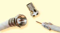
connectors to the coaxial
cable
Image courtesy of Szymon
Malański
to the satellite signal meter
Image courtesy of Szymon
Malański
to the antenna arm
Image courtesy of Szymon
Malański
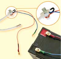
- Take the coaxial cable with only one connector, and strip the other end of the cable to reveal the metal core and the woven copper shield (figure 7).
- Plug the connector on that coaxial cable into the satellite meter’s second socket (labelled ‘power’ or ‘receiver’; figure 8).
- The other end of the cable now needs to be connected to your power source. Connect the woven copper shield to the battery’s negative terminal and the core to the battery’s positive terminal (figure 9).
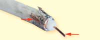
can be seen folded back along
the cable. The metal core
projects from the cable
Image courtesy of Szymon
Malański
power source
Image courtesy of Szymon
Malański
satellite meter and receiving
the signal from the LNB
Image courtesy of Szymon
Malański
You have now built a basic, mobile radio telescope that is light and manoeuvrable enough to transport and point at different objects by hand.
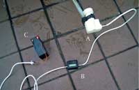
telescope. A: the LNB, on
which the radio waves will
be focused; B: the satellite
signal meter; C: the power
supply
Image courtesy of Szymon
Malański
If you wish to build a mounted device, you will need to attach it to an object (such as a heavy tripod) that allows you to adjust both the azimuth (the horizontal direction that the telescope is pointing in) and the altitude (how high or low it is angled).
Activities using your radio telescope
You now have a radio telescope that works on some of the same principles as the gigantic radio telescopes that are used to investigate the earliest days of the Universe, capturing radiation from very distant galaxies (see Mignone & Pierce-Price, 2010). Although your much smaller telescope cannot detect distant stars, you can use it to demonstrate to your students that the Sun and other objects radiate not only visible light but also radio waves. Furthermore, you can find the position of the Sun on a cloudy day, demonstrate that the surface of Earth emits radio waves, and locate satellites.
If you used a parabolic antenna to build your radio telescope, you will need to point its axis directly at the object you are observing. If you used an offset antenna, however, you must take into account the angle by which it is offset. Most manufacturers do not provide this parameter but it can easily be calculated (this can be an additional task for the students). In practice, the arm of the satellite dish on which the LNB is mounted indicates the direction from which the signal is received (figure 10).
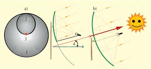
b) Cross-sections of an offset satellite dish (left) and a parabolic satellite dish (right), showing the angle of elevation (4)
Image courtesy of Szymon Malański
Observing the Sun
to locate the Sun
Image courtesy of Szymon
Malański
The Sun emits radiation across much of the electromagnetic spectrum. On a clear day, try pointing your radio telescope at the Sun and at a patch of empty sky. Compare the readings. Repeat the experiment on a cloudy day; the Sun’s location can easily be determined, despite the clouds. Ask your students why they think that visible light is blocked by the clouds but radio waves can penetrate.
You could also ask your students how they can distinguish the Sun’s radiation from a satellite signal, particularly as they sometimes appear close together in the sky. The answer: the satellite signal is polarised (horizontally or vertically) whereas radiation from the Sun is not. So if you rotate the radio telescope dish and the signal strength is unchanged, the signal is coming from the Sun.
Observing Earth
Objects around us, including buildings, plants, people and even the ground under our feet, emit radio waves, reflected from the Sun or Earth. Try comparing readings for different objects. Thanks to the auditory signal from the satellite signal meter, you should be able to detect the location of buildings and trees around you easily, even when blindfolded. To make sure that the signal does not come from the Sun itself, make sure you carry out these experiments by pointing the dish away from the Sun.
Detecting heat
Most astronomical phenomena produce electromagnetic radiation because they are hot. The higher their temperature, the shorter the wavelength they can produce. At around 5500 ºC, the Sun produces plenty of visible light as well as infrared and radio waves. Colder objects have to be detected using infrared or radio telescopes. You can demonstrate this by pointing your radio telescope at a hotplate as it heats up. It will only begin to emit visible light at around 700 ºC, but your telescope will detect the radio waves emitted well before that.
Satellites
We have built this simple radio telescope using satellite TV technology, which allows it to detect spacecraft too. Professional radio telescopes do this too sometimes – Australia’s Parkes Telescope was used to communicate with Apollo 11 during its mission to the Moonw1.
The best-known communications satellites (e.g. Hot Bird, Astra and Sirius) are in geosynchronous orbits around Earth, which means they do not move in the sky, and orbit above the equator. This makes them easy to find. The Wolfram Alphaw2 database provides the location of many satellites.
Be aware that during the spring and autumn equinoxes, the Sun shines above the equator and can interfere with satellite reception when the Sun and the satellite are in the same area of sky. Wolfram Alpha has a map of the Sun’s location relative to a satellite, so this is easy to avoid.
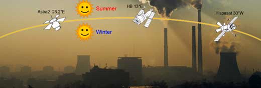
Image courtesy of Szymon Malański
Feedback
If you have suggestions for improving the telescope or for further activities, please leave a comment at the end of the online articlew3.
Acknowledgement
Our radio telescope was inspired by a working model built by Peter Kalberla, an astronomer at the University of Bonn, Germany, and demonstrated at his 2011 course ‘Hands-On Universe: Connecting classrooms to the Milky Way’w4 in nearby Bad Münstereifel.
References
- Mignone C, Pierce-Price D (2010) The ALMA Observatory: the sky is only one step away. Science in School 15: 44-49.
Web References
- w1 – Learn more about how the Parkes Observatory supported the Apollo 11 mission.
- w2 – To locate satellites in the sky, search the Wolfram Alpha database.
- w3 – Leave your suggestions for improvement and activities in the comments section at the end of this article.
- w4 – Find out more about the course that inspired this article.
- w5 – Learn more about Boguslaw’s planetarium (in Polish).
Resources
- For an activity to investigate radio transmission and the propagation of electromagnetic waves in air, see:
- Iscra A, Quaglini MT, Rossi G (2006) Introducing radio transmission with a simple experiment. Science in School 3: 39-42.
- To find out more about electromagnetic radiation and how it is used in astronomy, see:
- Mignone C, Barnes R (2011) More than meets the eye: the electromagnetic spectrum. Science in School 20: 51-59.
- The European Southern Observatory (ESO) is one of the partners in the radio observatory ALMA, the Atacama Large Millimeter/submillimeter Array, an ensemble of huge, high-precision antennas on the Chajnantor plateau in Chile’s Atacama region. Also on Chajnantor plateau is ESO’s radio telescope APEX.
- ESO is a member of EIROforum, the publisher of Science in School.
Review
If you would like your students to discover that the Sun or a hotplate emits a lot more than just visible light, that visible light is blocked by the clouds but radio waves are not, or that the electromagnetic spectrum consists of a variety of very interesting radiation; if you want your students to be able to find the position of the Sun on a cloudy day or to locate geostationary satellites; if you would like them to distinguish polarised radiation from non-polarised radiation; if you want to use a radio telescope in your lessons, constructed by your students and capable of helping you to teach all these topics and much more, then you will definitely be interested in the ideas presented in this article.
Using cheap materials and easy-to-follow instructions, you can build a simple but functional small-scale radio telescope. The activities suggested in this article are both interesting and applicable to a range of scientific topics (e.g. orbits, light, radiation and its effects on the body, and the electromagnetic spectrum), which can be covered in physics, astronomy and biology lessons.
Vangelis Koltsakis, Greece